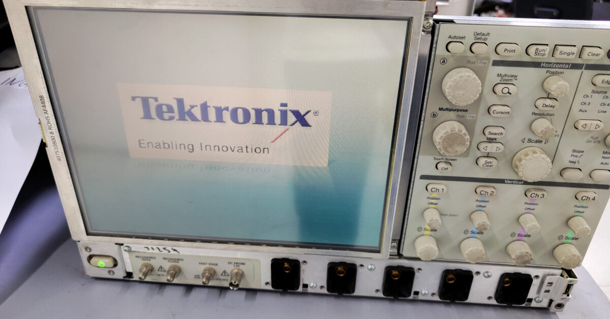
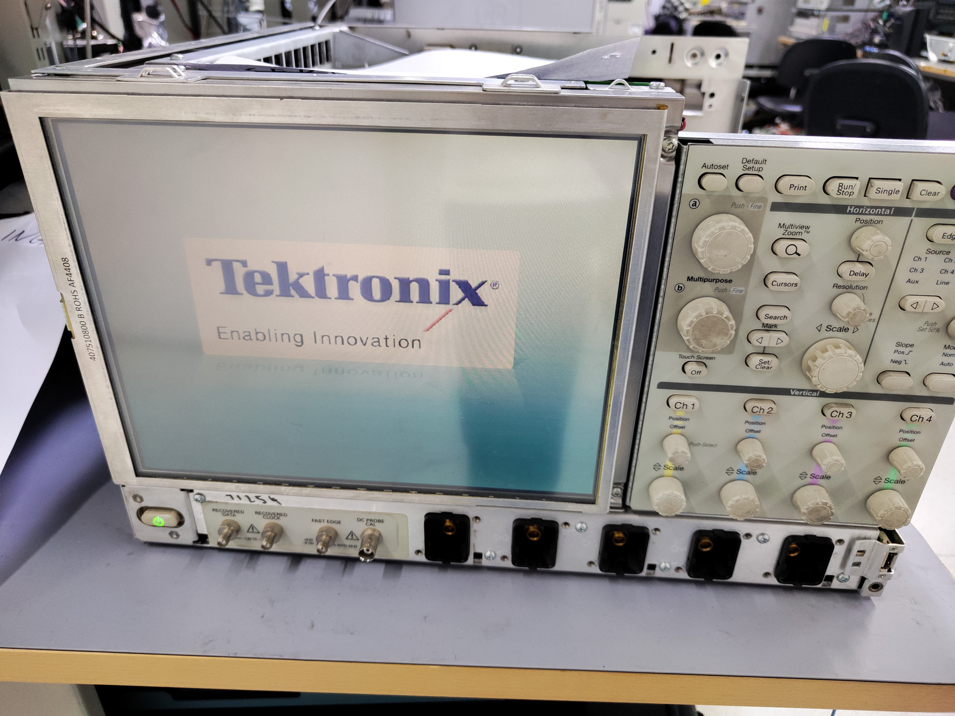
There is a DPO71254B at my workplace that has been abandoned for quite a while. I repaired it so that we can use it to debug (no cal though). This DPO71254B is made in 2008 and does not boot. The service manual is available from Tektronix. This scope is Windows-based and use a Pentium-4 based platform.
Diagnose and Repairing Power Backplane
When Power Button is pressed, the power indicator LED flashes. I torn down the unit and discover that there is fault indication on the power backplane. Occasionally the computer can boot, but it freezes on BIOS POST.
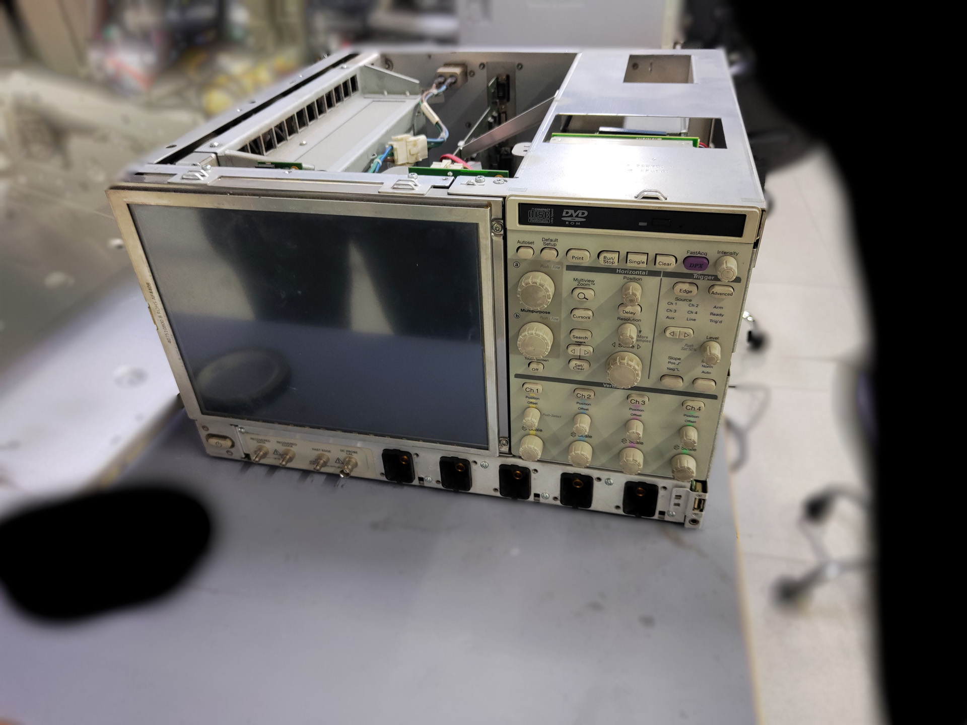
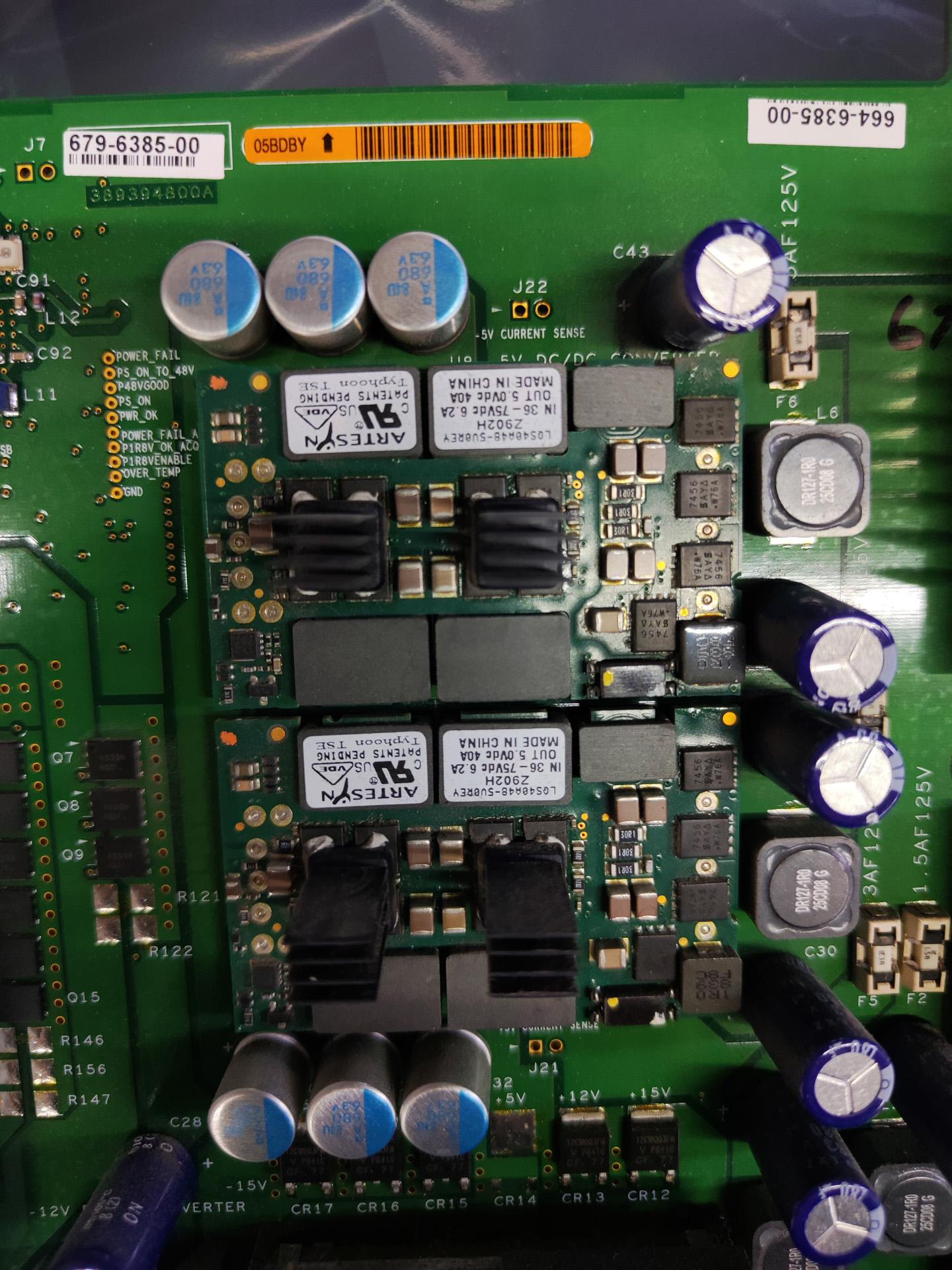
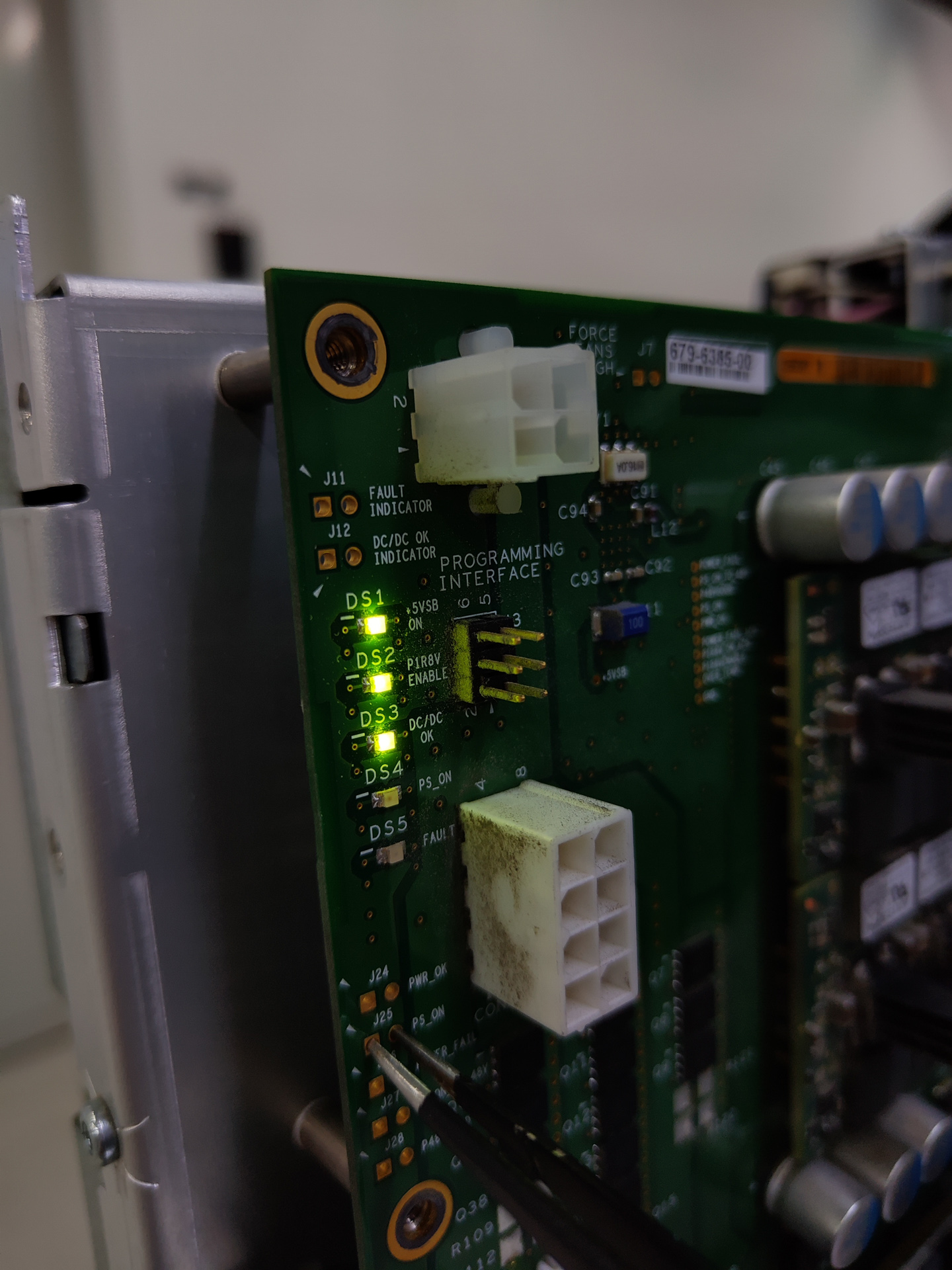
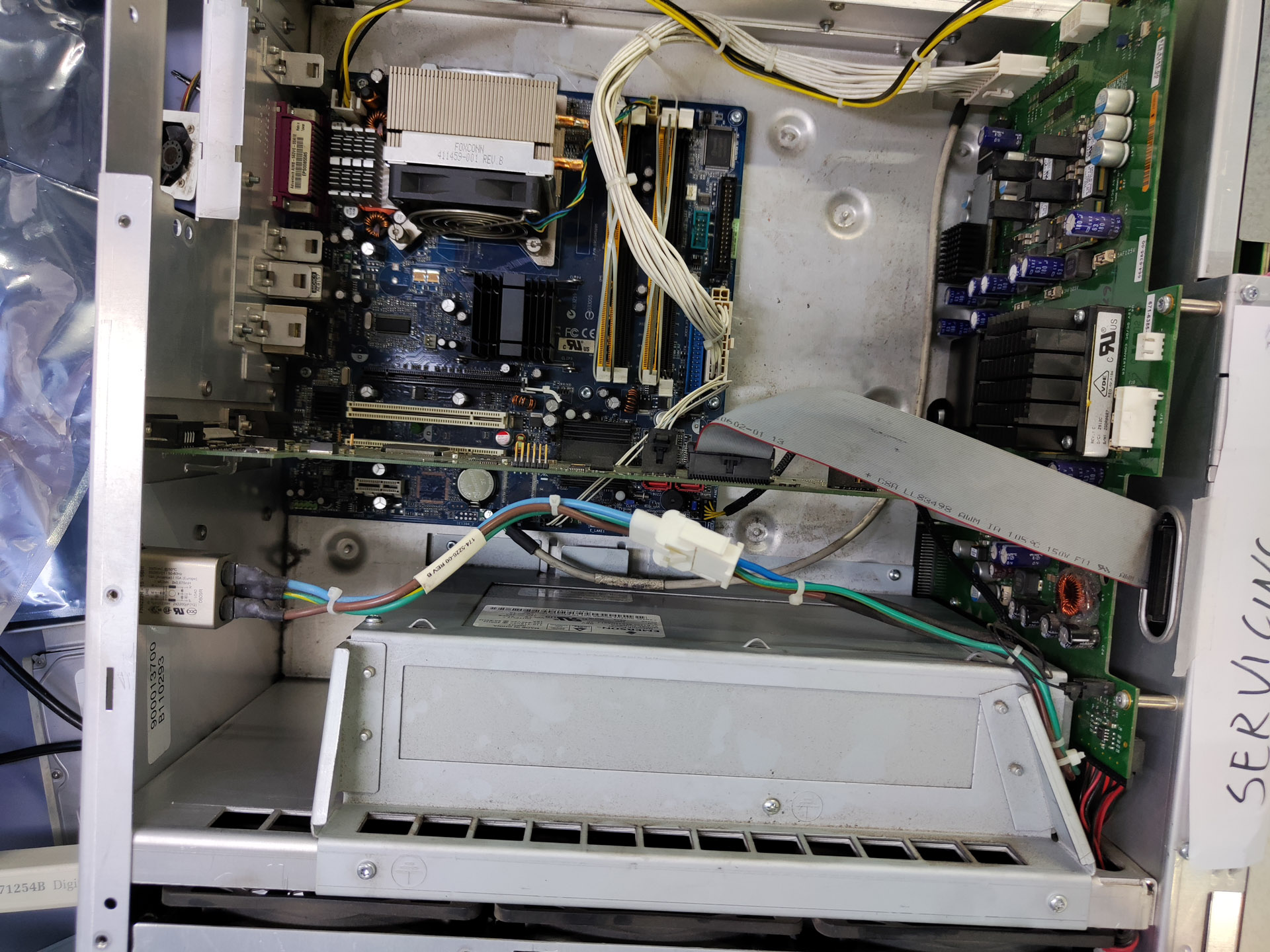
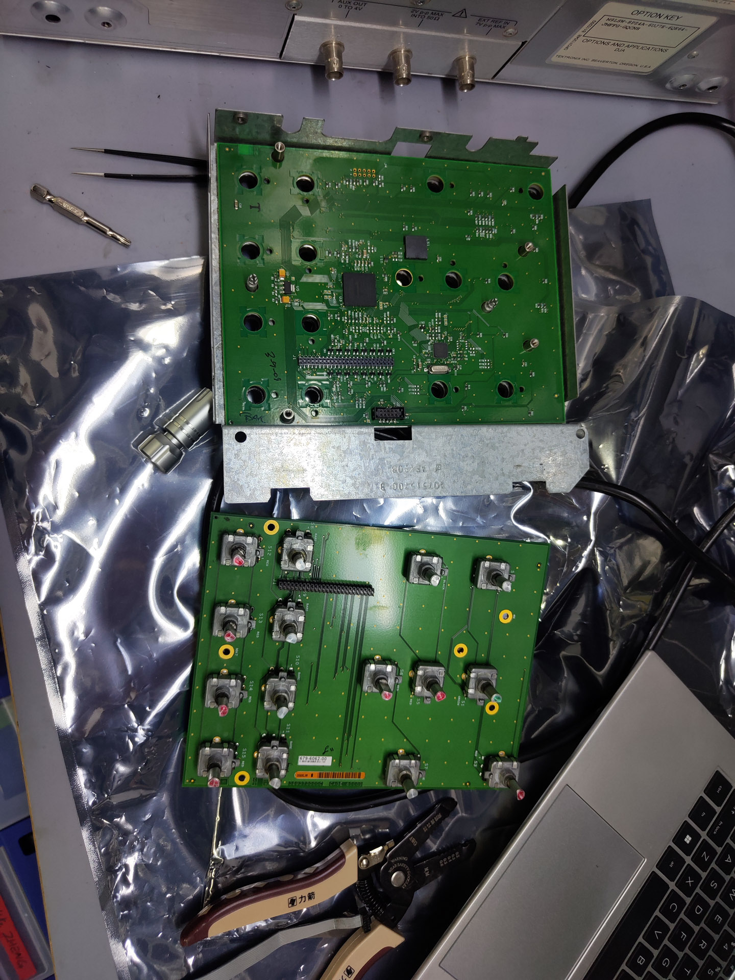
I quickly disassembled the whole upper part (everything except the ADC board, which is separated with sheet metal and is mounted in the base of the machine). I put together a test fixture to check the DC backplane board. This board is controlled by the PS-ON of the uATX motherboard. When I short the PS-ON to ground, the backplane board tries to boot but throw a fault LED.
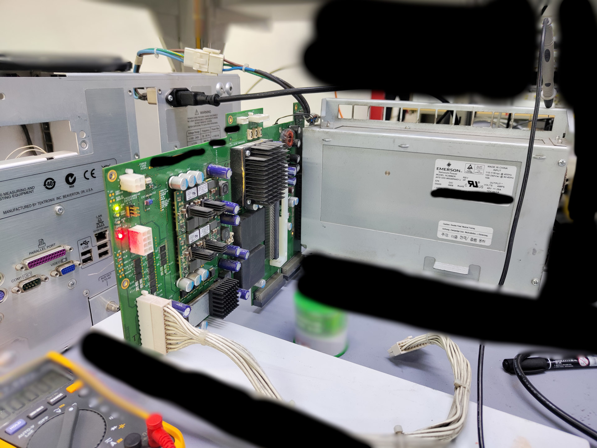
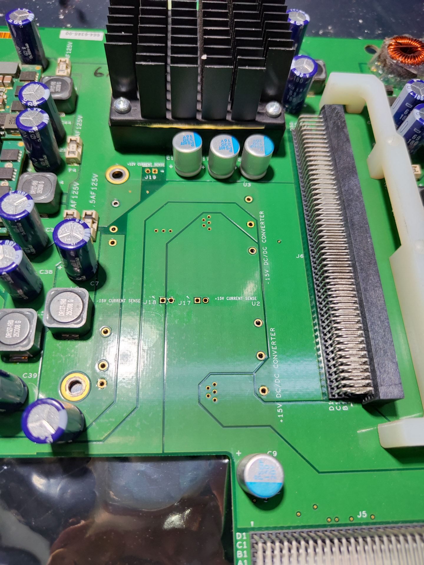
This backplane board connects to the large PSU which output 48VDC. It then convert the voltage to a bunch of voltage rails including 12V, 3.3V, 5V, -5V, 1.8V and +-15V using off-the-shelf DCDC modules.
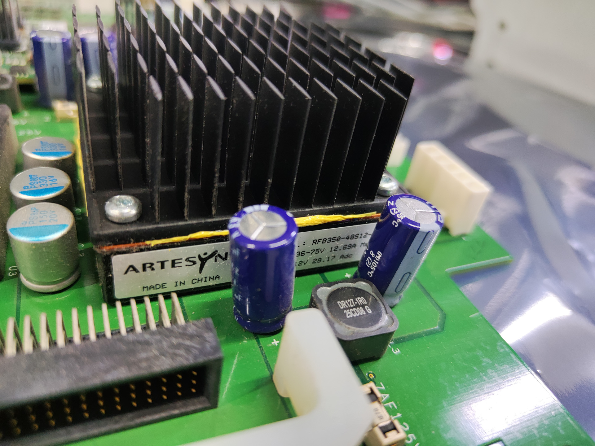
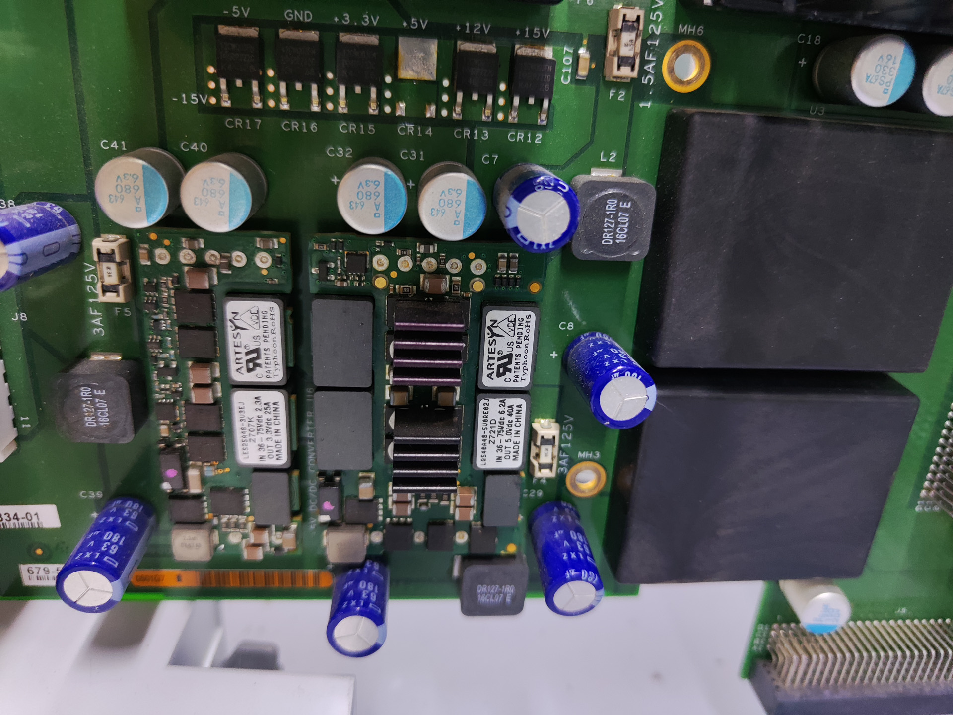
The board can still startup sometimes, so I checked the voltage when it can start, and the +15V and -15V is absent. +15V reads 12V which clearly is reverse fed from the 12V rail through the diode. Since +15V is the highest voltage rail, if it cannot boot, then nothing will start.
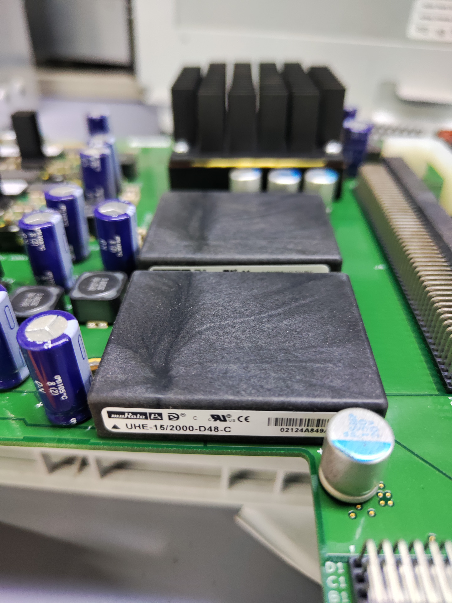
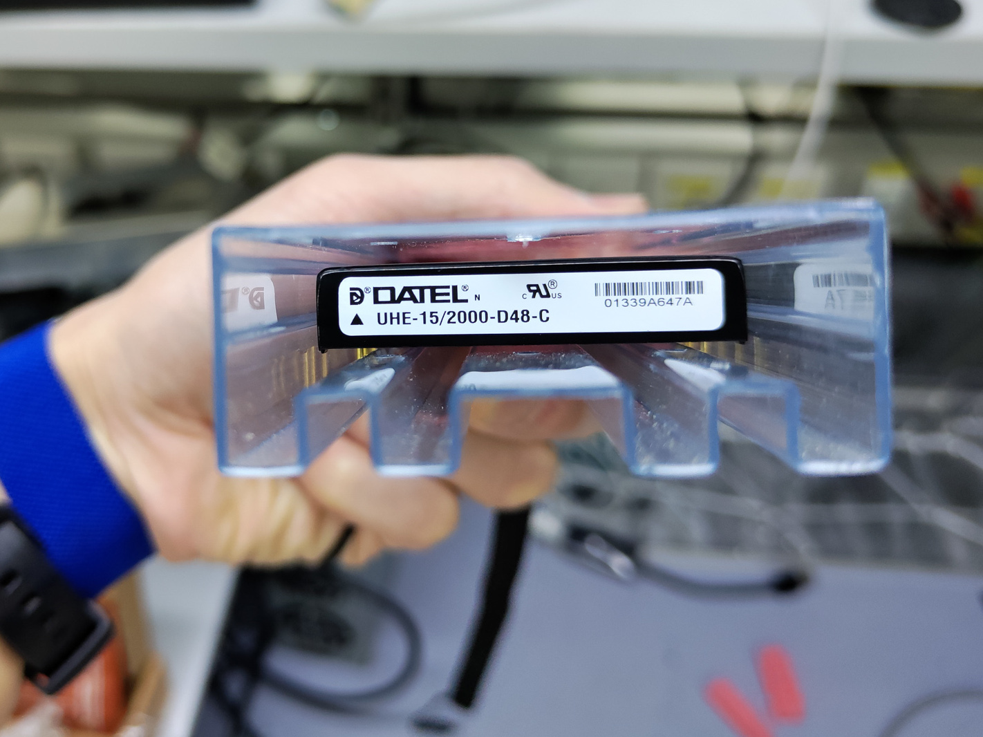
I fed +-15V into the board and it can start reliably, indicating no further issue. I also removed the +-15V modules (one for +15 and one for -15) and checked them off-board, they are all dead.
To fix this issue, I ordered 2 DATEL module that has same part number (same as the Murata ones used on the board, DATEL had been acquired by Murata but has since bought itself out again).
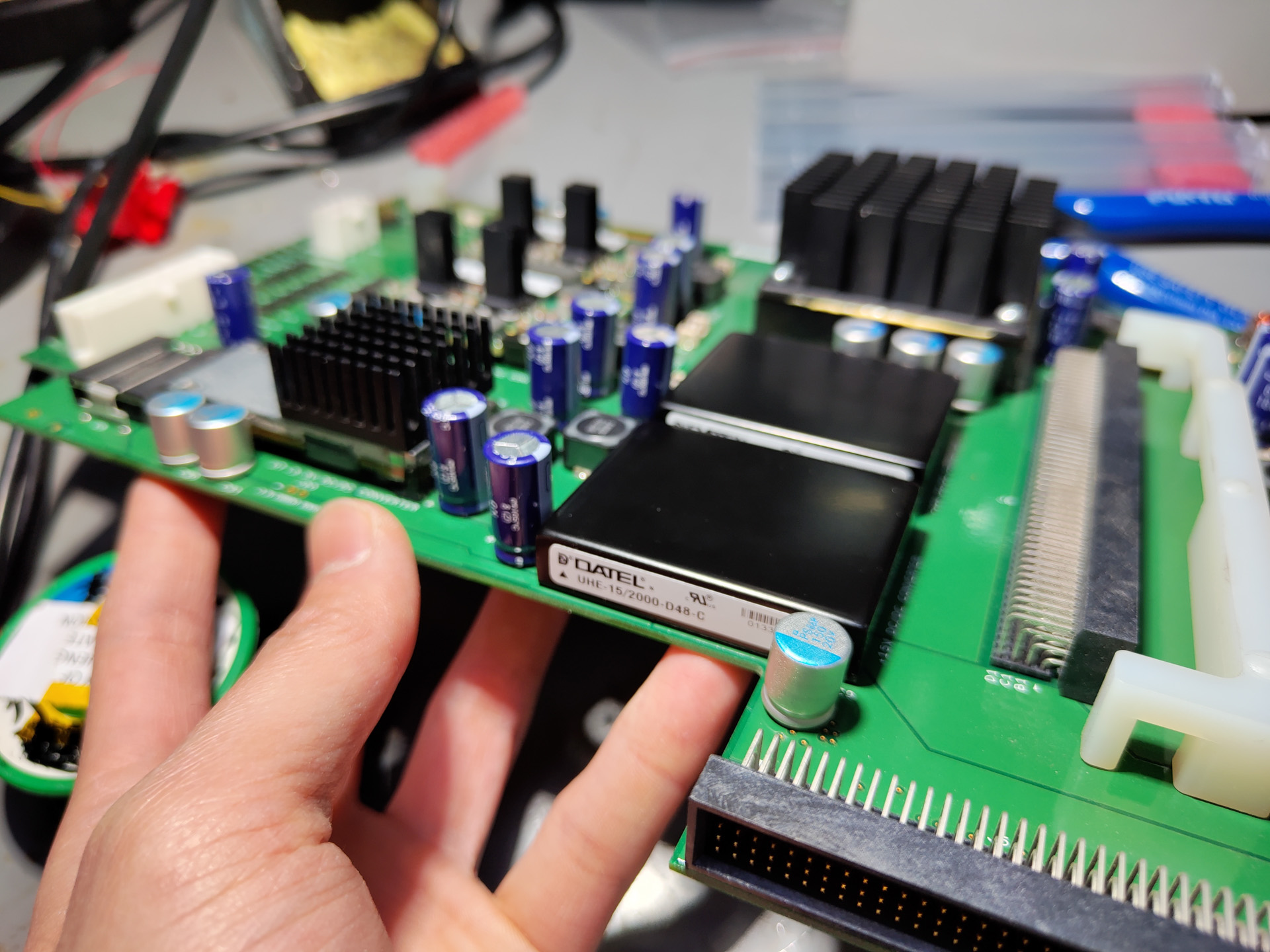
Once the modules arrived, I soldered them on, and the power backplane can now work (Try not to use tweezers as an electrical connection like shown below, in many situations it won’t end well……).
Fix the Computer
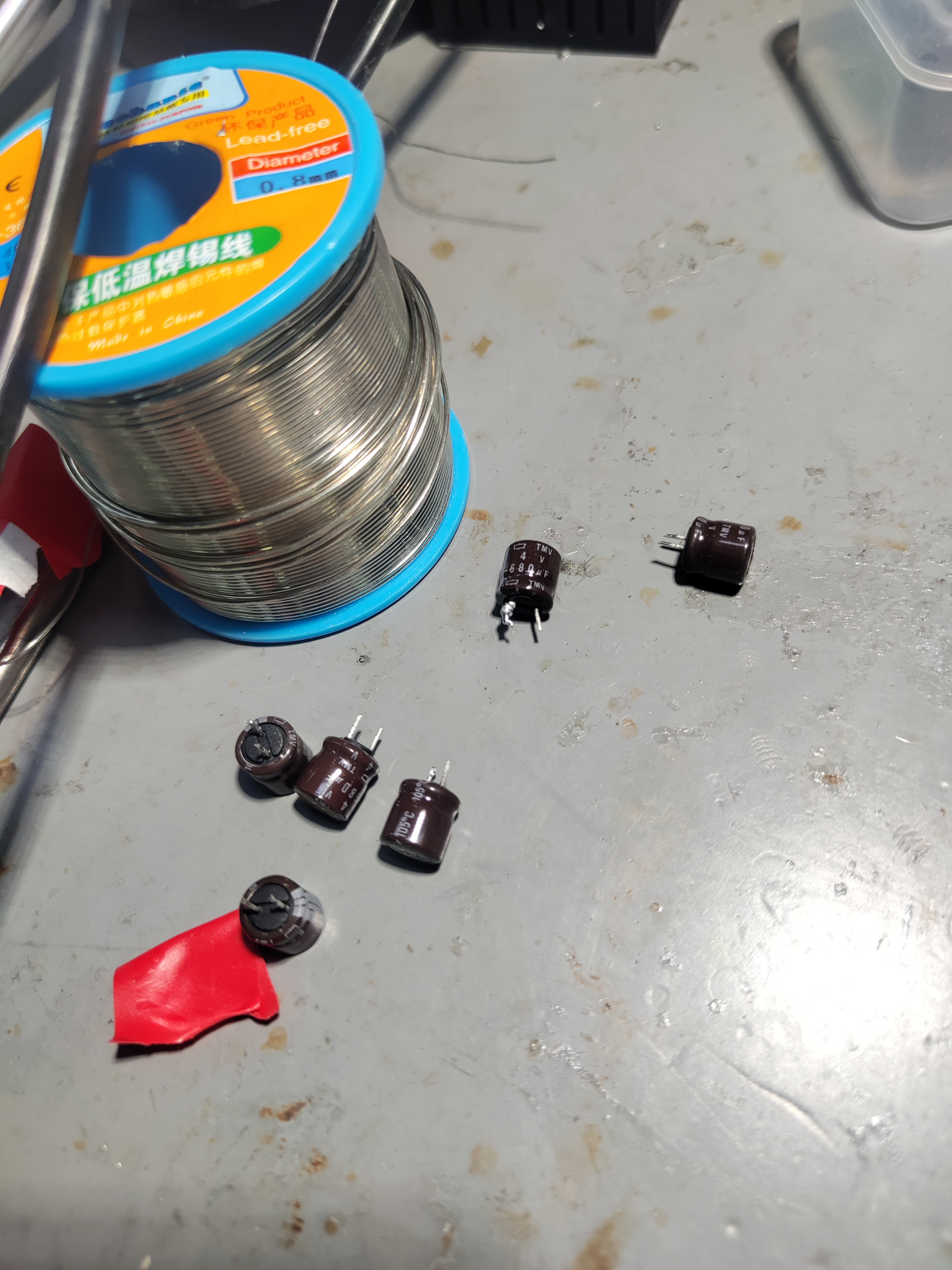
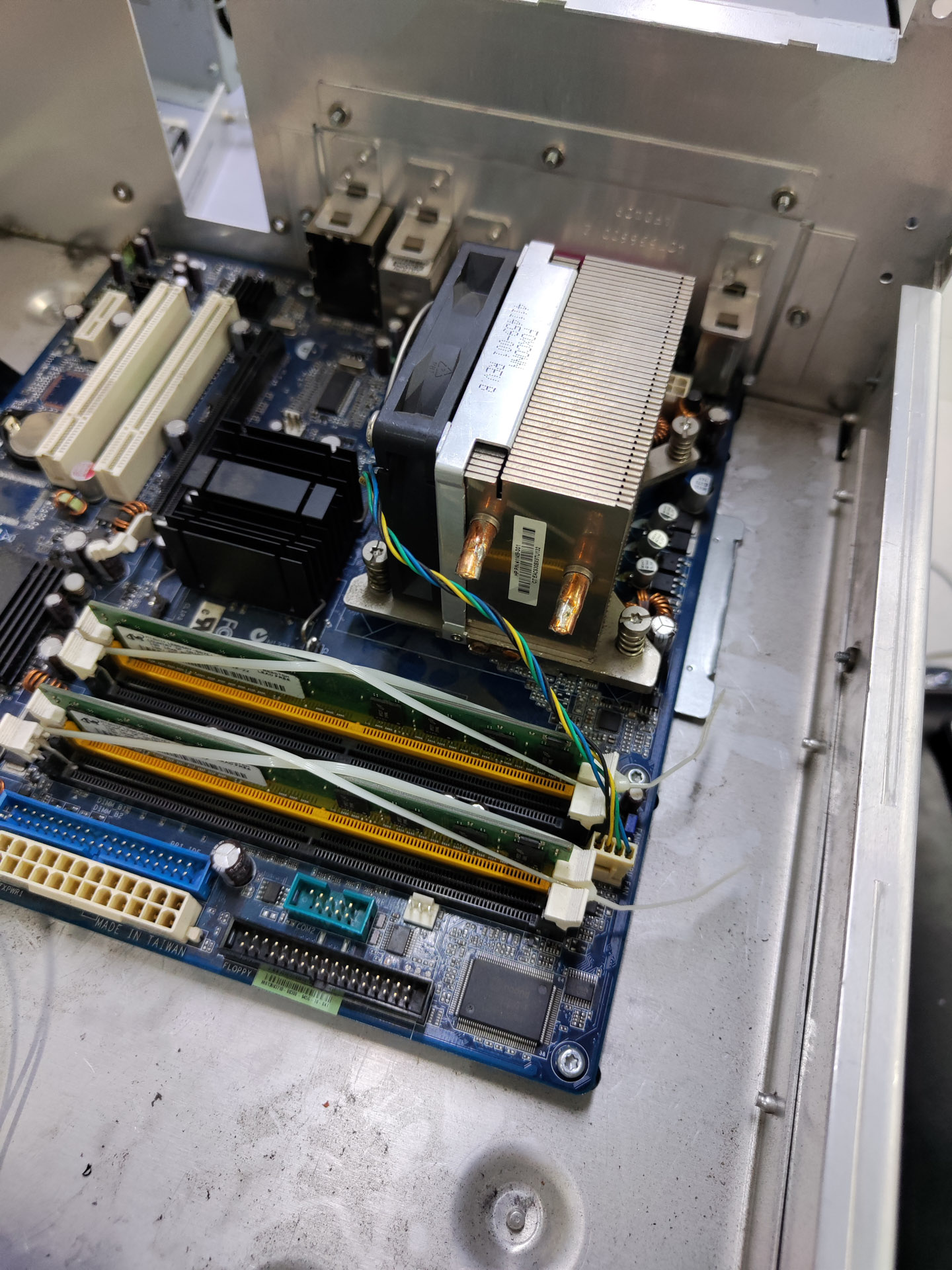
Next problem is to fix the computer. It’s also possible to just swap it out for another one, but we don’t have one in the lab. The issue is caused by dried-out capacitors in the CPU VRM area. These are easily fixable, just replace the capacitors.
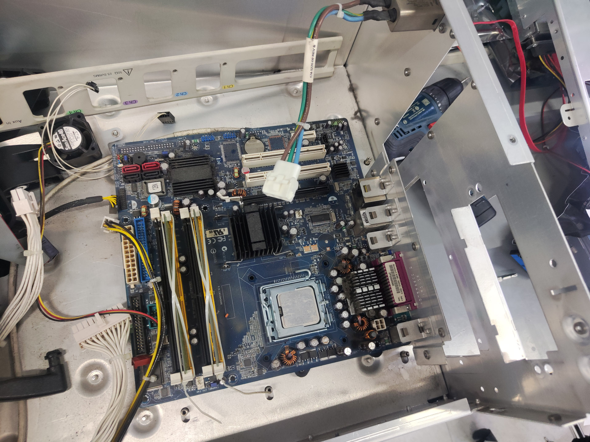
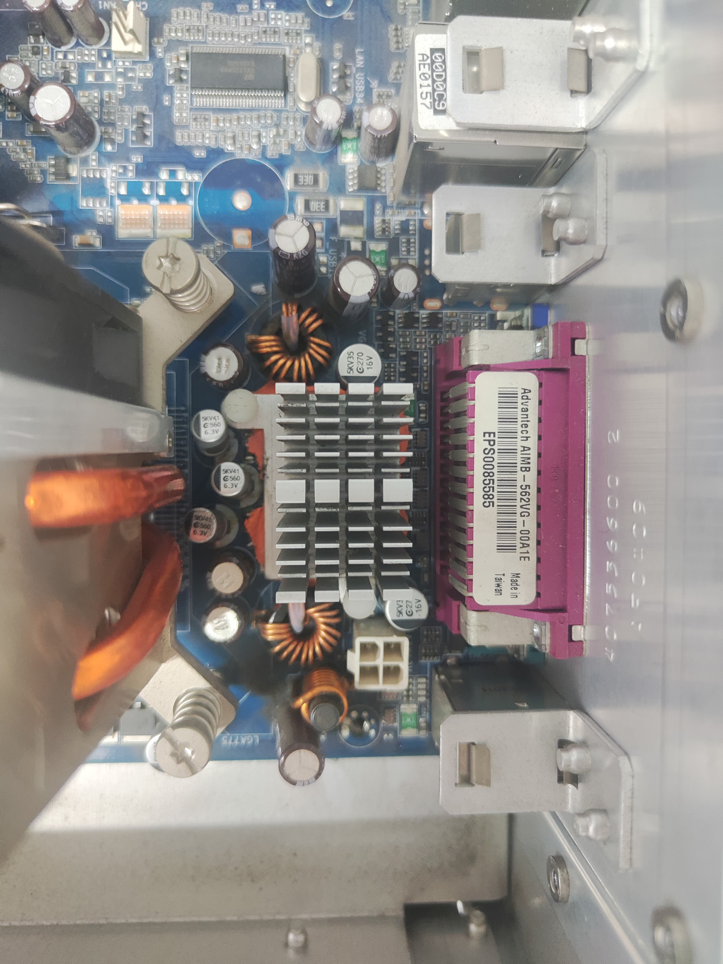
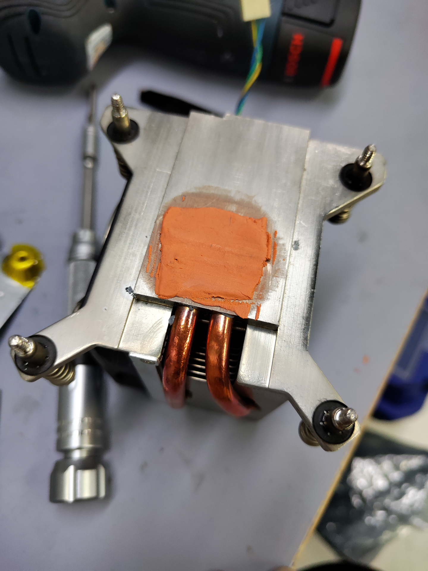
While I’m at it, I also replaced the heatsink and fan with an HP OEM one, and applied new thermal grease (putty actually, didn’t have grease on hand at that time).

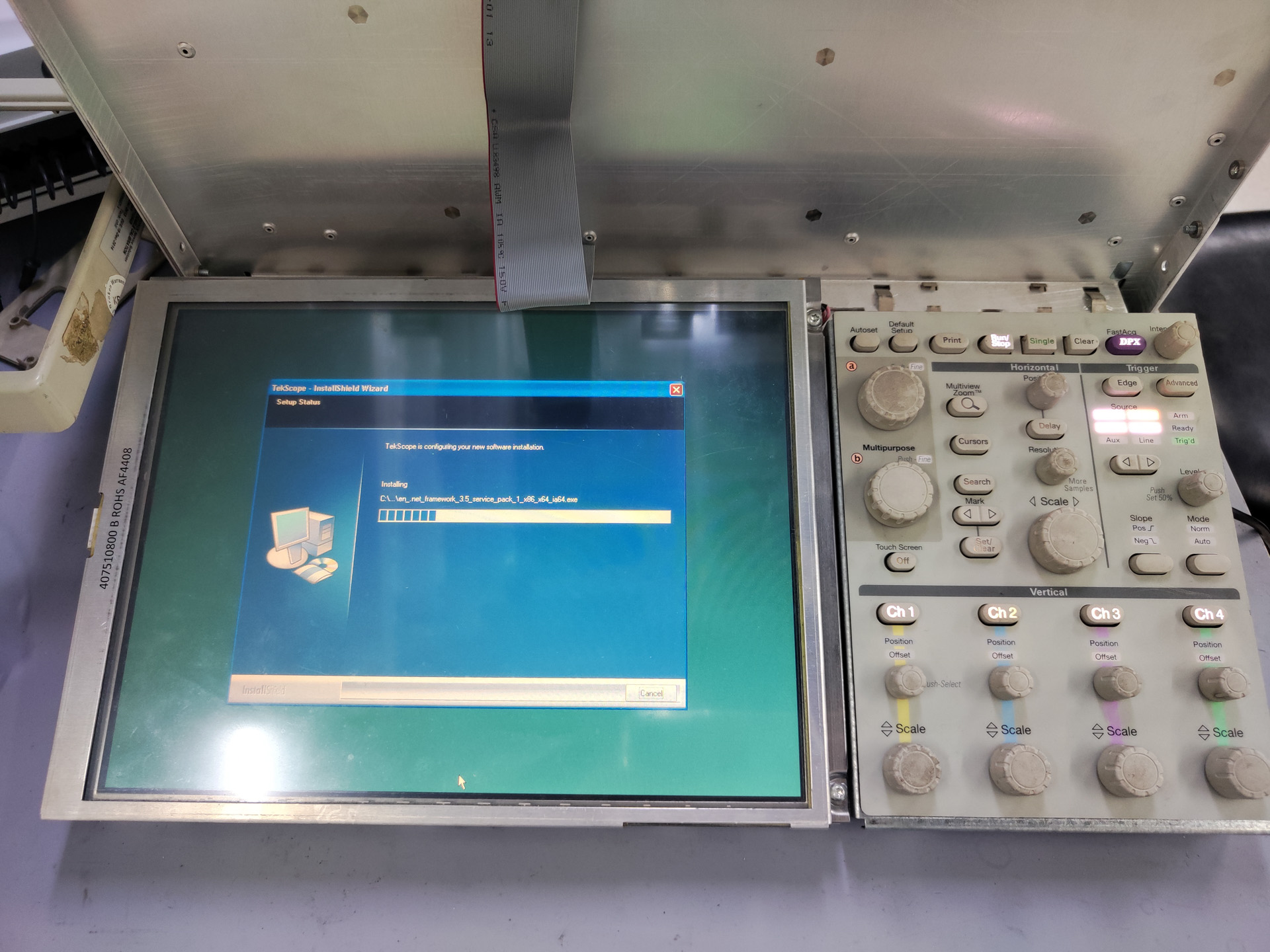
Now that the computer is fixed, it’s time to focus on the software side. I restored the operating system from Acronis, and installed the Deployment Package from Tektronix (As this is an older DPO70000B series scope, the software can be downloaded from the DPO7000 product page).
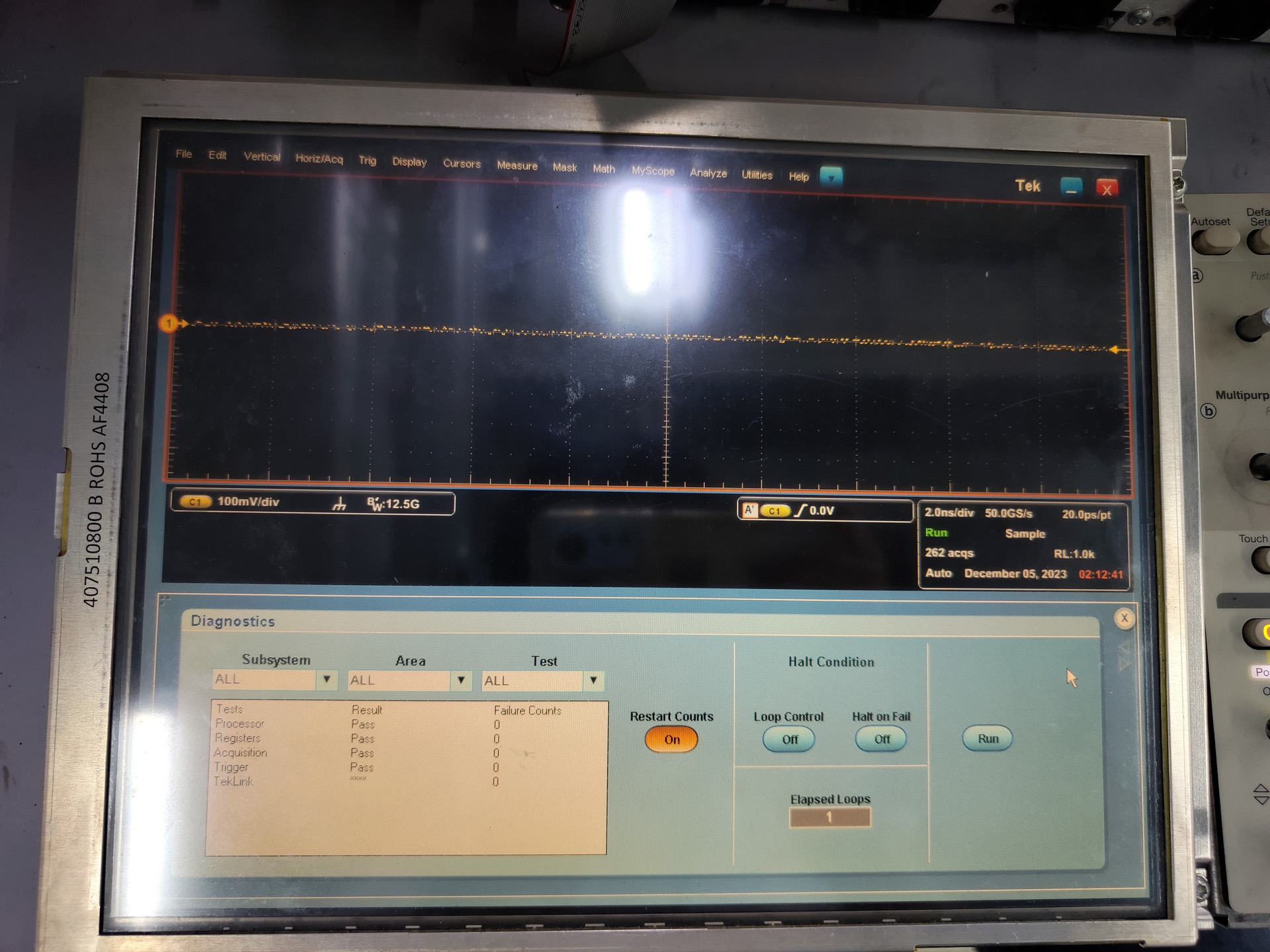
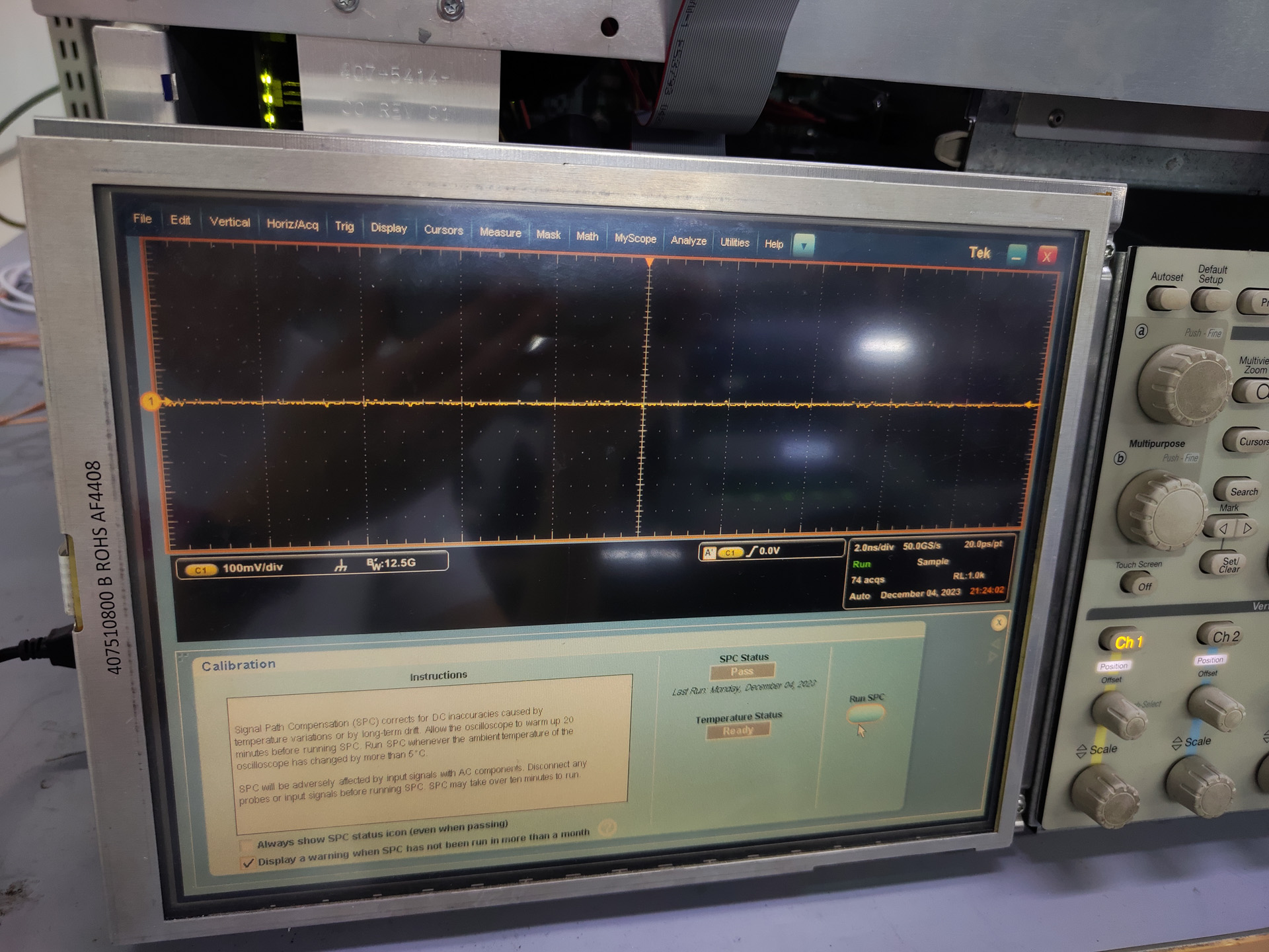
After install, everything checks out, self-test passed, the SPC has passed, all channels work.
Fix Clock PLL circuit
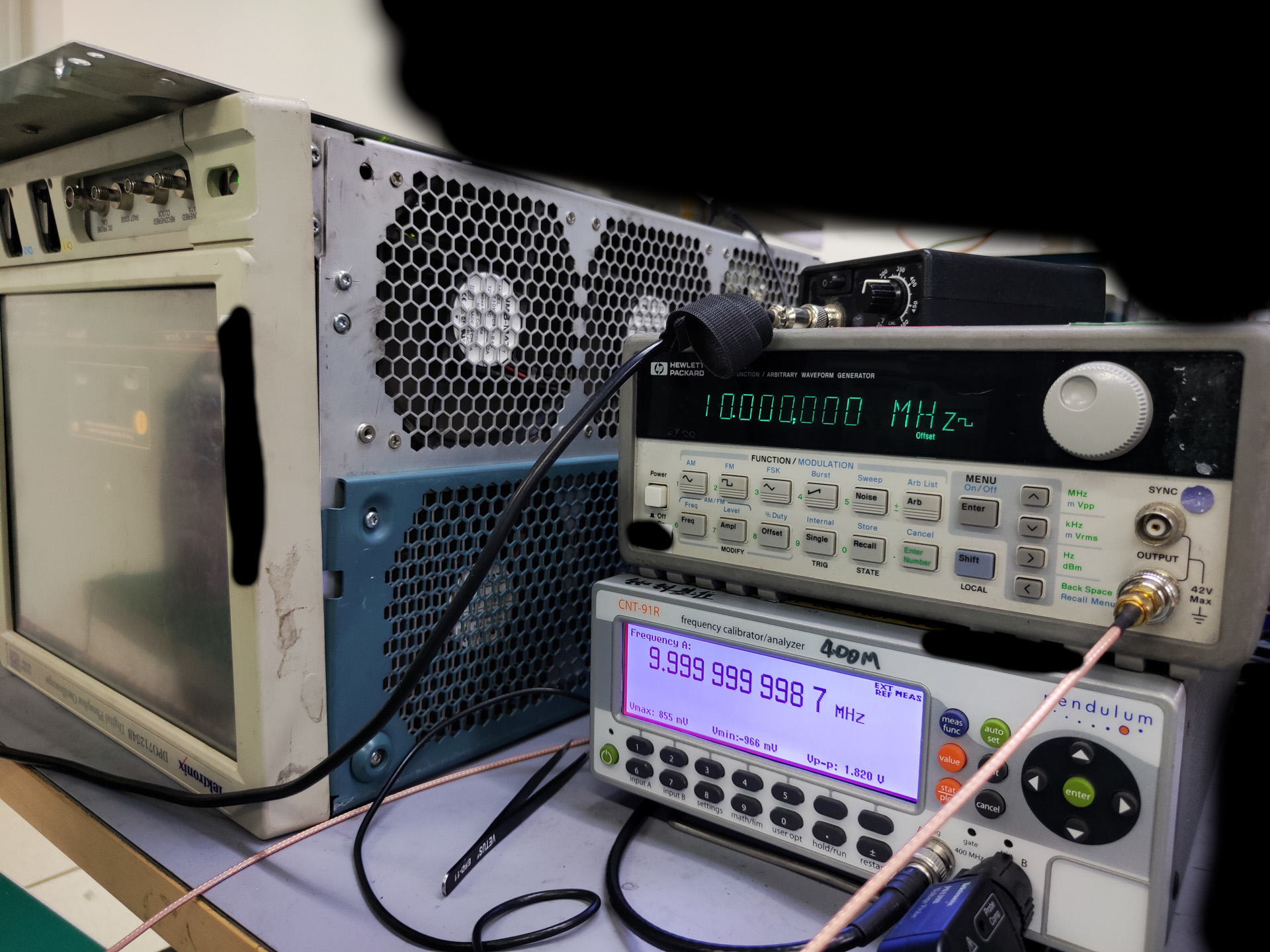
After I reassembled everything, I ran the scope for 24 hours. Then another problem emerged, the scope threw a code for reference clock loss of lock. I confirmed this by using a frequency counter to check the 10M ref out of the scope. It reads 10.00155M which is way off. So I had to tear open the bottom part to reveal the ADC board. It’s best not to touch this part unless it’s absolutely necessary, since these machines are extremely expensive and delicate.
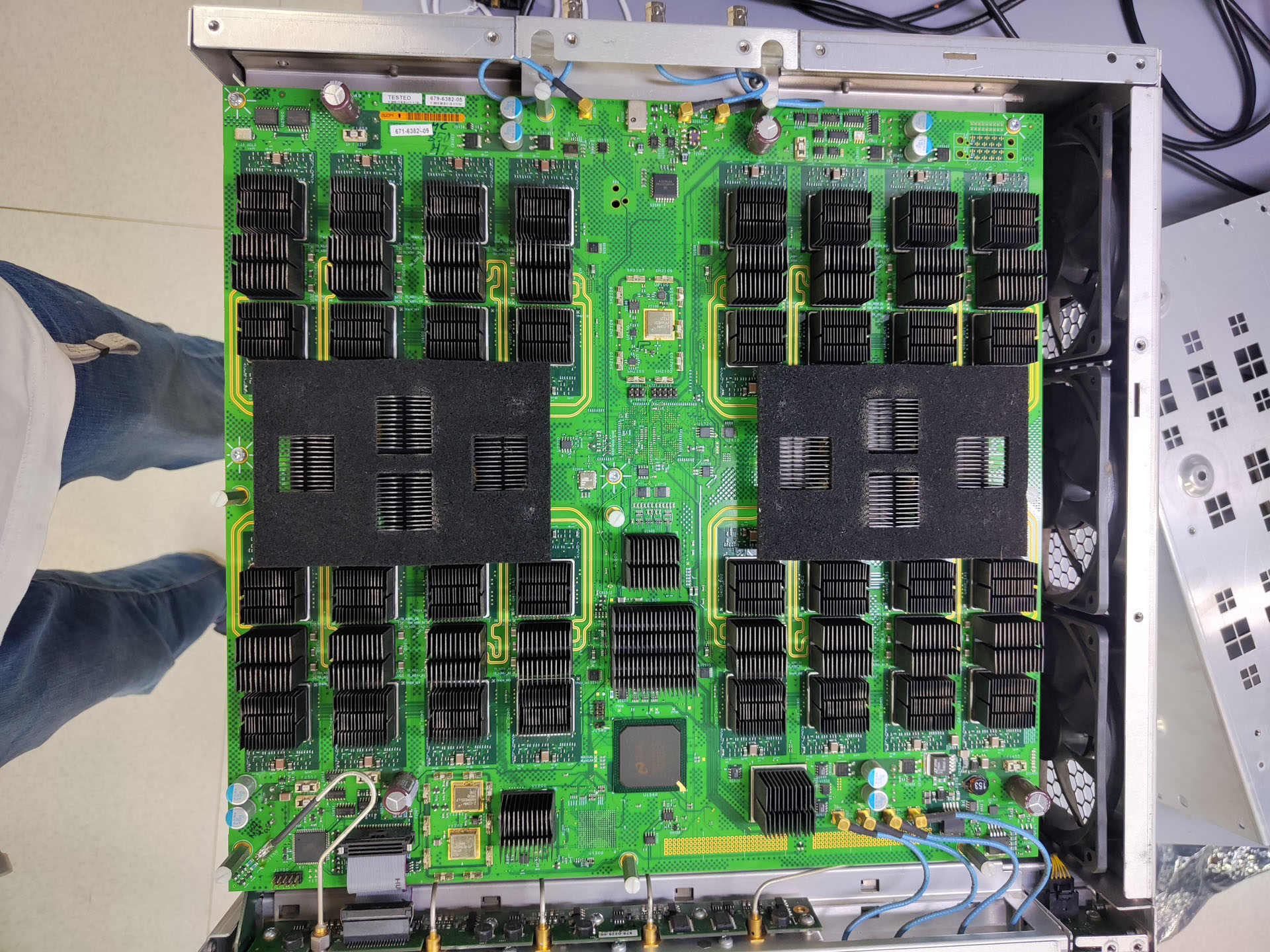
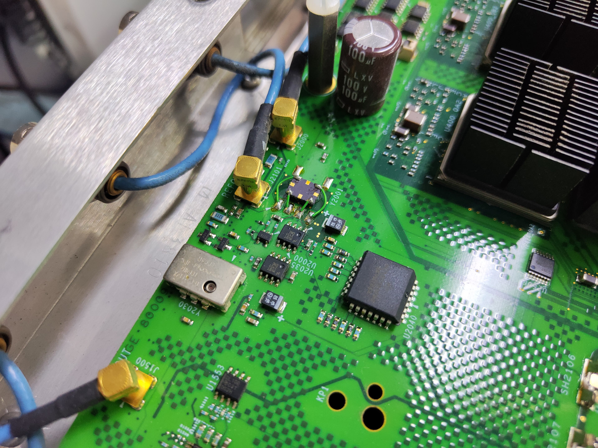
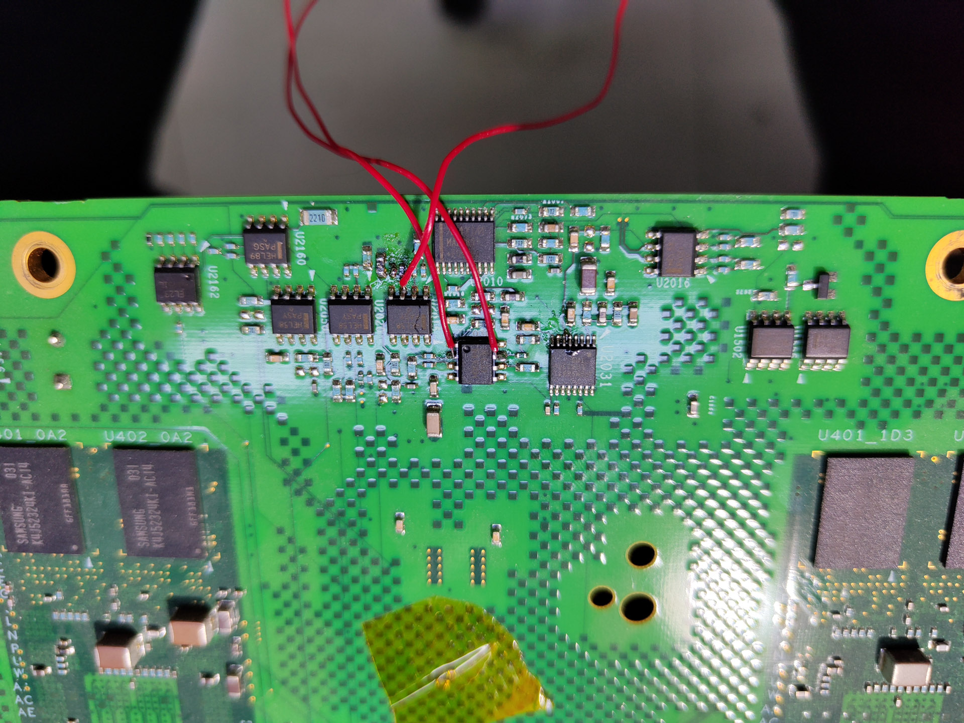
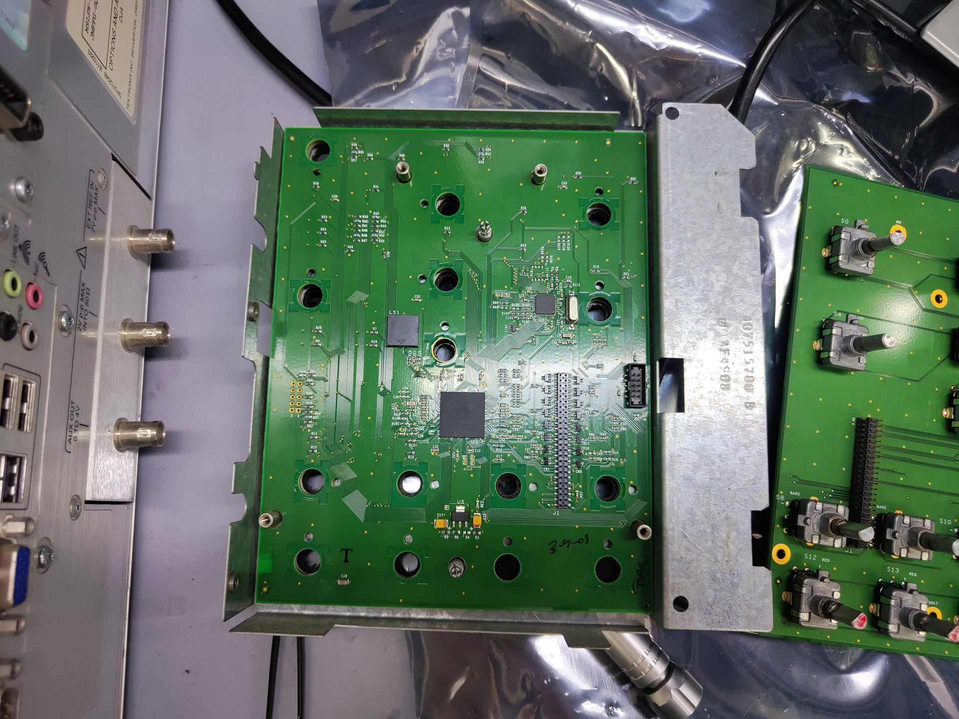
This entire ADC board along with its supporting sheet metal structure can be taken out as an drawer like assembly and it is connected to the backplane board with BTB connectors located in the bottom right of the photo. In this photo the clock part is located at the top center part, consisting of a 10M TCXO for high stability and a 100M VCXO for low phase noise. A PLL chip locks the VCXO to the reference (either built-in TCXO or external ref in). The upside-down SMT TCXO is a factory job, not repair.
As can be seen, this part of circuit is pretty complex involving all kinds of logic circuit, including ECL, CMOS and TTL, gates, buffers, dividers and muxes.
At first the clock circuit cannot lock, the PLL control voltage will go up to maximum as soon as it powers on. But if I replace the TCXO with a AWG and bring the frequency first to match the PLL output voltage and bring it down slowly, it can actually lock at 10MHz. After a few days though it stopped to lock at all.
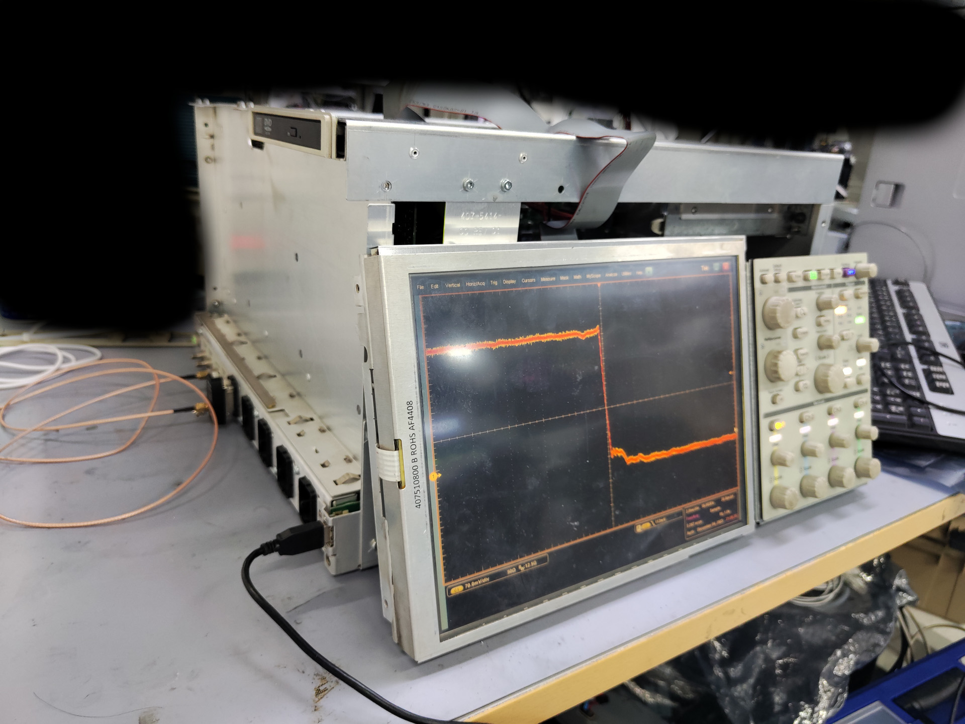
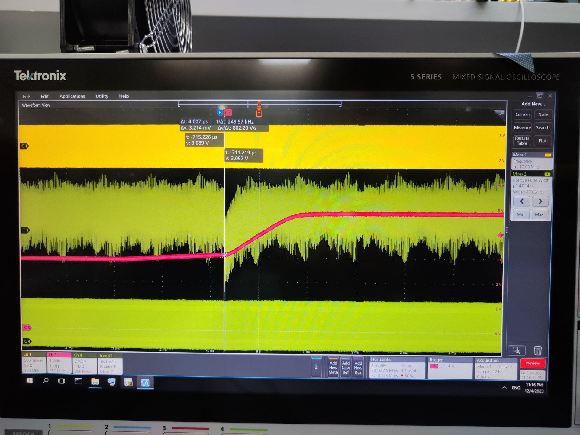
I caught the moment the PLL chip lost lock on scope. The magenta trace is the PLL control voltage output. The signals are there, but the PLL chip does not recognize it.
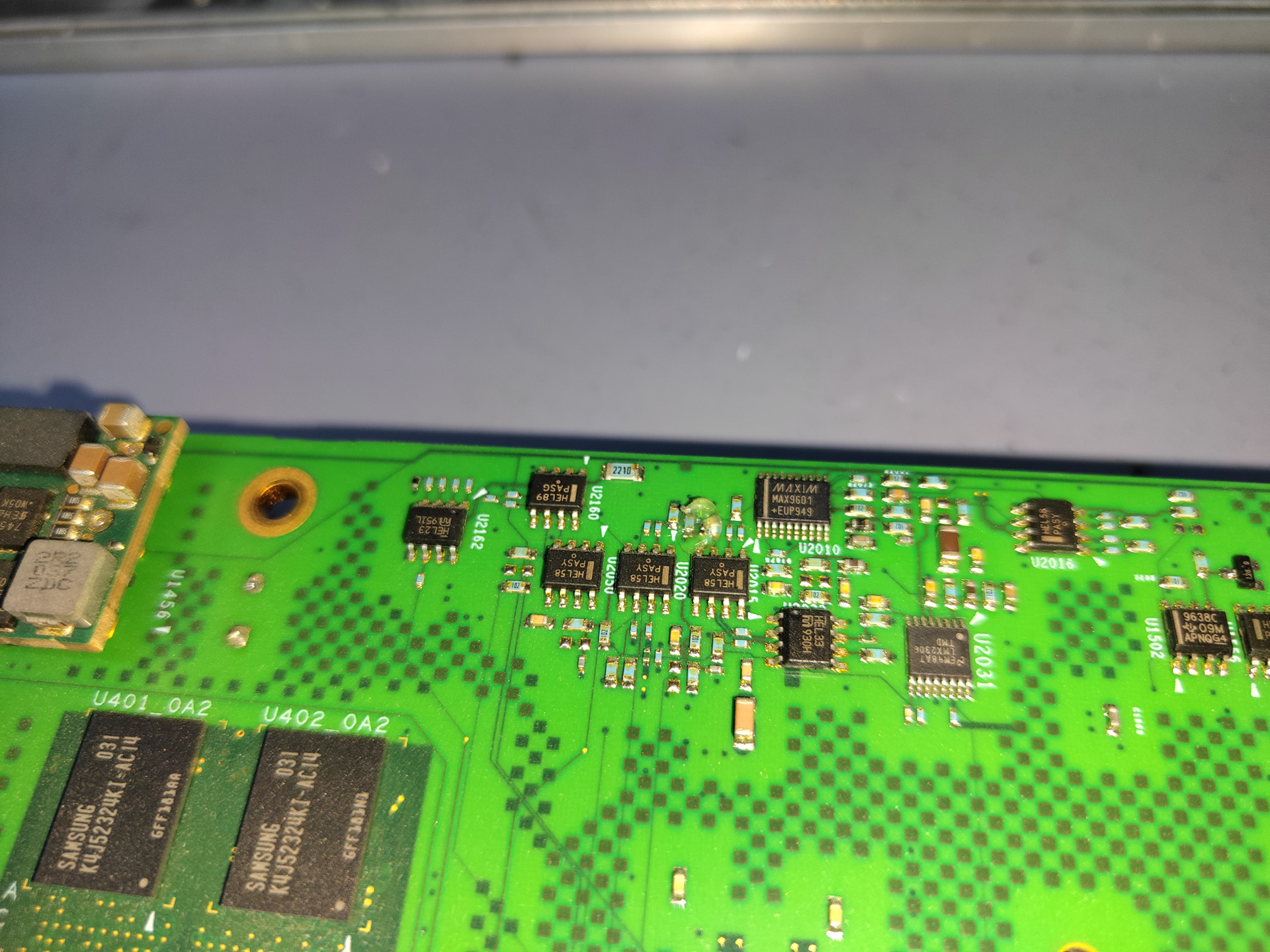
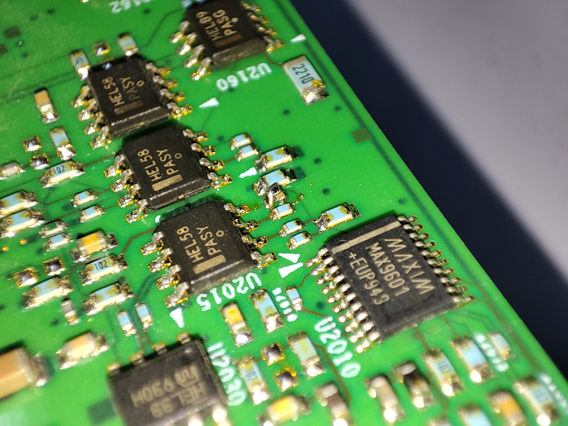
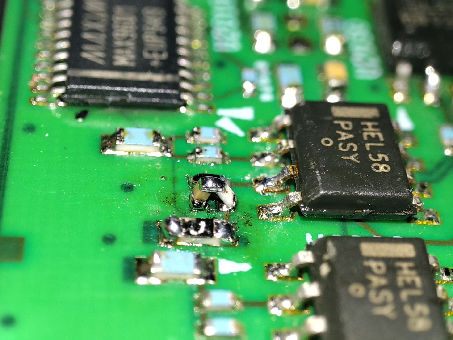
The issue is simple, the factory hand-soldered resistor-capacitor tombstone has failed. It seem to be failing under high temperature. It took me a very long time and some reverse engineering to located the issue though. I replaced the resistor-capacitor with new ones.
Finishing up
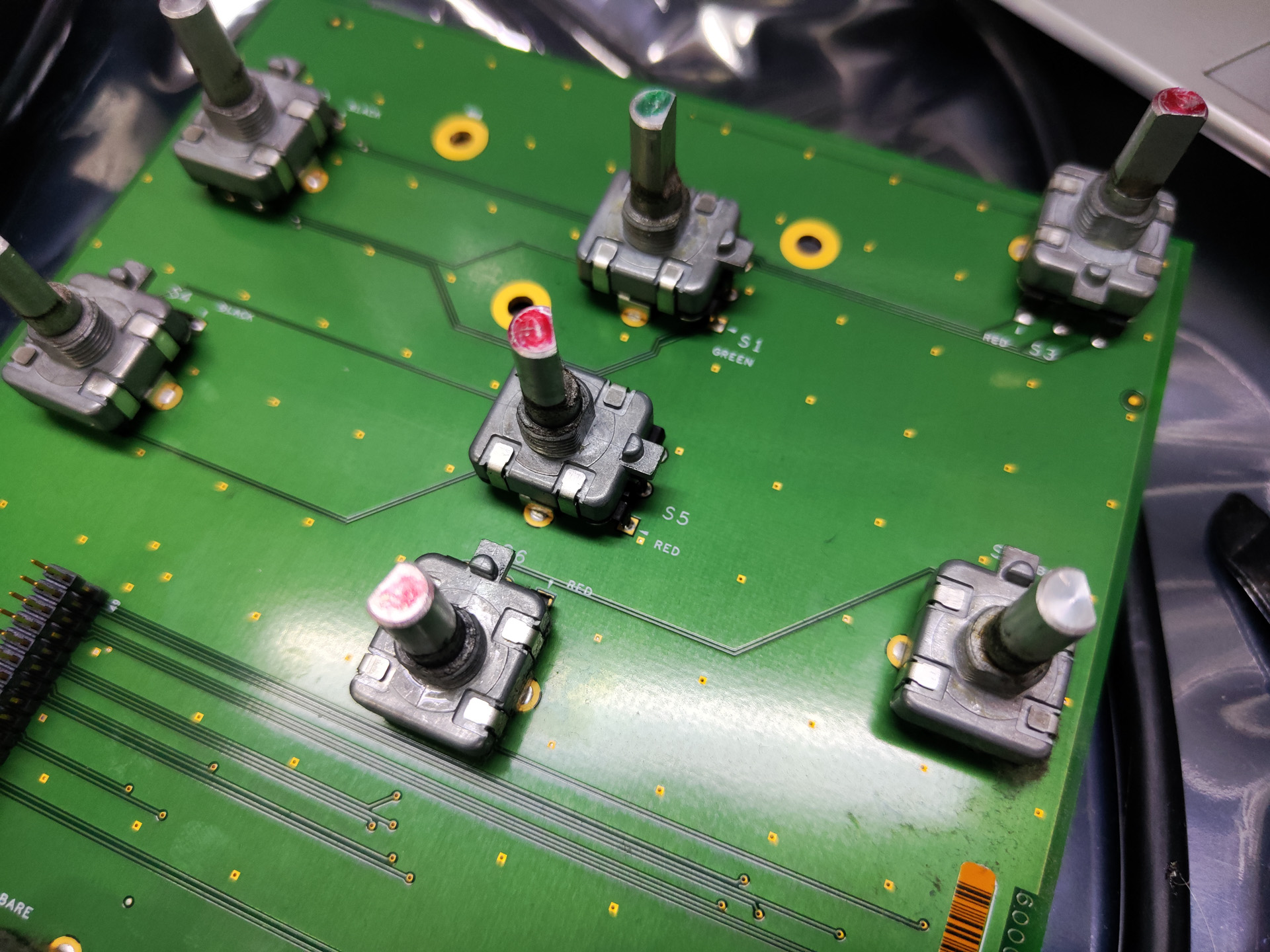
For the last part I cleaned the rotary encoders on the panel board. Just blasted them with contact cleaner and they work very well now. (Do not use contact cleaner on potentiometers though, it will destroy them. Use spcified Deoxit for pots or use pure ethanol alcohol)
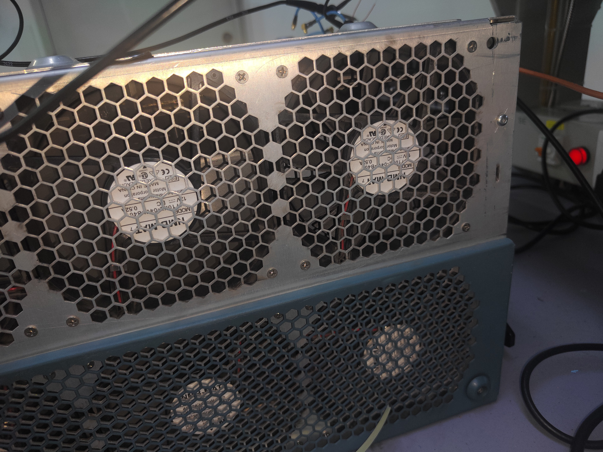
I also swapped the fan tray from another DPO70404 which is soon to be scrapped. The one that is currently on this scope has 2 fans failed. I wonder if this has been the cause of all these issues.
Well done – very good troubleshooting, especially the clock PLL.
Also nice restoration of the D-50 and Triton.
Mike Kirk
Chicago, IL USA